Determination of the Effective Length Factor for Non-Prismatic Columns in two-Span Gable Frames
Mohammad Behjati-Avval1 * and Vahidreza Kalatjari2
1
Shahrood branch, Islamic Azad University,
Shahrood,
Iran
2
Department of Civil Engineering,
Shahrood University of Technology,
Shahrood,
Iran
http://dx.doi.org/10.12944/CWE.10.Special-Issue1.53
The concept of effective length is the only common method for designing columns without nonlinear structural analysis. In the past, due to the complexity of the analytical equations that govern the column stability, effective length factor for columns with variable cross-section was determined approximately through diagrams. In the recent years, with the introduction of powerful mathematical software, the analytical mathematical equations (slope-deflection) and the effective length factor can be accurately calculated. Many studied have been conducted on the design of columns with variable cross-section in single-span gable frames. However, no study has addressed the two-span frames which are often used in industrial buildings. In this paper, a mathematical analytical method is presented for determining the effective length factor of non-prismatic columns in two-span gable frames. The accuracy of the analytical results was examined though stability analysis using ABAQUS. Finally, a number of practical diagrams were presented for determining the effective length factor of the columns in such frames.
Copy the following to cite this article:
Behjati-Avval M, Kalatjari V. Determination of the Effective Length Factor for Non-Prismatic Columns in two-Span Gable Frames. Special Issue of Curr World Environ 2015;10(Special Issue May 2015). DOI:http://dx.doi.org/10.12944/CWE.10.Special-Issue1.53
Copy the following to cite this URL:
Behjati-Avval M, Kalatjari V. Determination of the Effective Length Factor for Non-Prismatic Columns in two-Span Gable Frames. Special Issue of Curr World Environ 2015;10(Special Issue May 2015). Available from: http://www.cwejournal.org/?p=10956
Download article (pdf)
Citation Manager
Publish History
Introduction
Industrial single-story single- or multi-span frames with gable roofs are used to cover large spans in factories, warehouses, repair shops, garages, and aircraft hangers. In the not so distant, trusses were used to cover large spans; however, frames with variable cross-sections and moment-resisting connections are now widely-used in industrial structures.
Column is a member of frames. Their design is important for a structure to stay in its place under the loads. Theoretically, column is the only member that bears axial loads. In columns, the shear force and bending moment is zero. Beam-column is a member in which, in addition to the axial force, the shear force and bending moment are also significant. Buckling is an important phenomenon that distinguishes the design of column from other structural elements. A Column that buckles under load in a structure does not contribute to load-bearing, and other member would undertake the column’s load-bearing responsibility to prevent the structure from collapsing.
The use of members with variable sections in industrial frames makes it possible for the places with high bending moment to have larger moment of inertia, and thereby, greater section modulus. The section of industrial frames is generally I-shaped, where the flange dimension is fixed along the member length, but the wing height is considered dependent on the bending moment of the member.
In the frame design, effective length is used to show the contribution of other members of the frame in the compressive strength of the respective member. Researchers have developed a number of charts that readily determine the frame buckling loads and the effective lengths of columns. Theoretically, the effective length factor, k, for a column of a frame is obtained from the structural stability analysis. Galambos provided the factors for single- and two-story frames with wide spans (Galambos et al., 1960 ). Determining the effective length factors using the diagrams proposed by the Structural Stability Research Council (SSRC) (Johnston et al., 1976) provided by Julian-Laurence (Salmon et al., 1990) is a method approved by the AISC (Chicago, ILL,1986). and CAN-S16.1-M84 (Ontario, Canada,1984). In this method, the effective length factor is directly calculated in terms of the ratio of nodal bending stiffness at the ends of the column. Determination of effective length factor by considering the behavior of column in the inelastic range was proposed by Yura (Yura et al., 1971). The buckling differential equation of a simply supported column with variable cross section was solved in (Ermopoulos et al., 1997). The boundary conditions were then applied, and the characteristic equation for determining the critical load for a simply supported column was obtained. Ermopoulos (Ermopoulos et al., 1997) argues that if the column has other end conditions, solving the differential equation and obtaining the buckling load would be very difficult. Therefore, in variable sections, it is more efficient to use approximate methods to obtain the buckling load. Timoshenko (Timoshenko et al., 1908).provided diagrams for calculating effective length of the members with variable moment of inertia using the Rayleigh-Ritz method and selecting a power series as a function of deformation after buckling through simulations. These diagrams are also approved by AISC.
Stability Analysis of Frames With Non-Prismatic Members
For the stability analysis of frames with non-prismatic sections (Figure 1), an alternative approach is to simplify the analysis of variable cross-section member. This can be done though segmenting the member into several members with constant sections and analyzing a stepped structure. Although such an approach will simplify the problem, it increases the amount of computing time and volume, causes inevitable errors, and reduces the accuracy. Such disadvantages have caused the exact calculation of the stiffness matrix of a members with variable cross sections to be very ​​important.
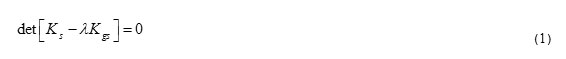
To analyze such frames, first, the stiffness matrix k6*6 and geometric matrix k'g6*6 of a bending frame element with linear fillet section was extracted using the finite elements. The stiffness matrix, ks, and geometric stiffness, k'g6*6 of the frame system was then studied using the techniques of structure matrix analysis. Finally, the critical buckling load factor of frame, λ was obtained using the principles of structural stability and though solving the eigenvalue equation (1) by MATLAB.
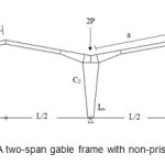 |
Figure1: A two-span gable frame with non-prismatic sections Click here to View figure |
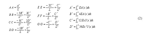
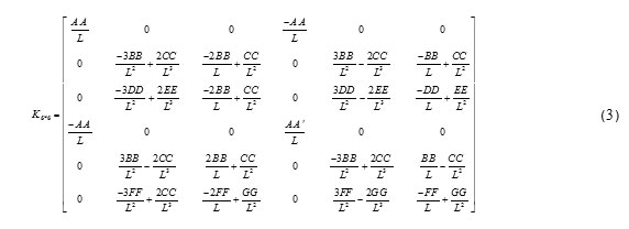
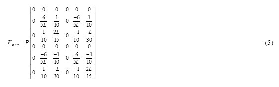
The stiffness matrix k6*6 and geometric matrix k'g6*6 of a bending frame element with variable section is defined by equations (2) to (4) (Yura et al., 1971).Bu substituting the equation (2), stiffness matrix (3) is obtained:
So we have
To construct the geometric matrix, by assuming a constant axial force along the element length, we have:
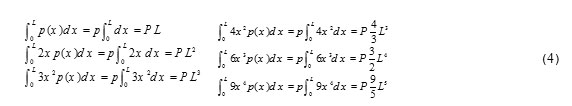
By substituting the equation (4), and similar to the previous case, the geometric matrix is:
Now that we have the stiffness matrix k6*6 and geometric matrix k'g6*6 of each frame member in the system coordinate, the matrices are assembled, and the stiffness matrix KsNF x NF , and geometric matrix KgsNF x NF of the entire structure is extracted through the structural matrix analysis techniques. The NF index represents the total number of independent degrees of freedom of the structural systems. Finally, the eigen-value problem is solved using a program written in MATLAB.
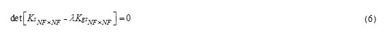
The solution to the above eigen-value problem is NF values for λ, where λi is the critical buckling load coefficients of the entire system. This means that for these values, the determinant equals zero, and the system buckles and becomes unstable.
Since we are looking for the minimum critical buckling load, the minimum λ is the critical buckling load coefficient of the studied structural system.
The critical load is obtained through finding the minimum λ and multiplying it with the axial forces of the member under buckling.
Since the aim of this paper was to determine the effective buckling length factor of two-span gable frames with non-prismatic sections, in order to comply with usual methods of structural design codes and regulations, especially AISC, the critical buckling load of each compressive member was assumed equal to the Euler buckling load of the same member with a smaller end characteristics and same buckling effective length (k y L). Elastic effective buckling length k y of the compressive load with variable section was then obtained.
Thus, by obtaining the minimum critical buckling load factor λmin equation (6) yields:
Pcr = λmin.P (7)
Where, Pcr is the elastic critical buckling load of the member, and P is the axial force of the member under buckling which was obtained though stability analysis under the specific loads.
If the compressive member (Figure 1) has a variable section with linear depth variations, and the section area and section modulus at the smaller end of the member are A0 and I0, and at the larger end of the member are A0 and I0, then, by equating the Euler buckling load and the elastic critical buckling load, Pcr, we have:
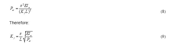
Where, is the effective length factor of elastic buckling of the compressive member under with variable fillet section.
Selecting the Variations Function of Depth, Area, and Section Modulus
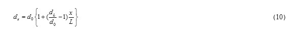
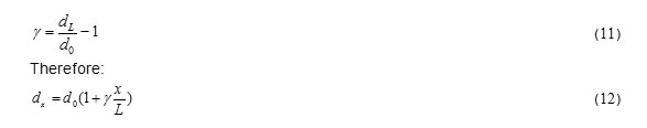
Based on the assumption of linear variations in the depth of the section, the variation function of section depth in terms of the member length is:
According to AISC, λ is defined as:
In general, for the sections of linear fillet columns, the section area and section modulus variation functions in terms of member length can be determined with a good approximation with equations (13) and (14):
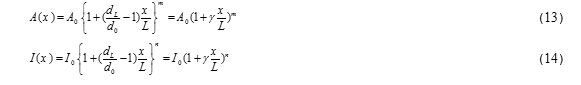
Where, m and n are the shape functions of the section and are a function of section’s dimensions and shape. By letting x=L, A (x)= AL and I (x) = IL in equations (13) and (14), we have:
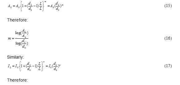
The shape factors m and n can be readily calculated if the dimensions of the start and end points are known.
Validation
To validate the results obtained from the computer program, they and the results obtained by ABAQUS and reference are shown in an example.
Example 1
Determine the effective length factor of a gable steel frame with non-prismatic sections (Figure 2)which has the geometric specification listed in Table1. (Saffari et al., 2008)
Table1: The specifications of the frame sections
|
Section No. |
dx (cm) |
Ix (cm4) |
Section No. |
dx (cm) |
Ix (cm4) |
|
1 |
20 |
1527 |
6 |
60 |
18181 |
|
2 |
30 |
3691 |
7 |
56 |
14259 |
|
3 |
40 |
7054 |
8 |
48 |
10743 |
|
4 |
50 |
11817 |
9 |
42 |
7888 |
|
5 |
60 |
18181 |
10 |
36 |
5552 |
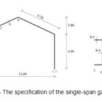 |
Figure2: The specification of the single-span gable frame |
Table2: Result example 1
|
ABAQUS |
Reference method |
Presented method |
|
|
Critical Buckling load (ton) |
83 |
85 |
86 |
Determination of the Effective Length Factor
The frame model introduced in the computer program for determining the effective length factor is shown in Figure 1. This model assumes a symmetric frame with load shown in Figure 1. Given the basic assumptions for the sections of columns and beams, moment of inertia of columns, and the ratios of effective length factor for columns of the frames is determined in the special cases.
The parameters that affect the length factor and are used in the output diagram are as follows:
β: Ratio of the fillet length to the total length of the beam
γ: Dimensionless ratio of the frame sections
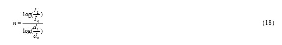
n: According to equation (18)
Im/I1: The ratio of moment of inertia of the small sections of the middle column to that of the lateral column
C1: Lateral column C2: Middle column
F/H: The ratio of the vertical projection of the angled members to the column height
Figure 3 and 4 show two output graphs of the program for determine the effective length factor of two-span gable frames with different supports in the special cases.
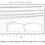 |
Figure3: Diagram for determining the effective length factor for hinged support |
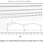 |
Figure4: Diagram for determining the effective length factor for fixed support |
Example 2
Consider a two-span gable frame with non-prismatic column shown in Figure 6.
Determine the effective length of the columns of the frame using the diagram.
The frame geometry specifications are:
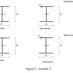 |
Figure5: Example 2 |
The required ratios are as follows:
Table3: Example 2
|
β |
n |
γ |
Im/I1 |
LH |
FH |
|
|
Lateral column |
0.4 |
2.242 |
1.23 |
1.814 |
3.33 |
0.25 |
|
Middle column |
0.4 |
2.262 |
0.94 |
1.814 |
3.33 |
0.25 |
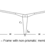 |
Figure6: Frame with non-prismatic members |
According to the diagram of Figure 4 presented for this case, the effective length factors of the lateral and middle columns are 2.02 and 2.2, respectively.
Conclusion
A simple method for fast and accurate calculation of the effective length factor of two-span gable frames with non-prismatic members was proposed here. The effective length factor can be obtained through determining the buckling load of the columns in such frames and using the obtained diagrams. The results can be utilized in the preliminary and final design of two-span gable frames and when comparing them with the software results.
References
- Ermopoulos, J.C. Equivalent Buckling Length of Non-Uniform Members. Journal of Construction of Steel Research, 42(2), 141-158(1997).
- Galambos, T. V. Influence of partial Base Fixity on Frame Stability. Journal of Structural Division, ASCE, 86(5), 85-108(1960)
- Johnston, B.G. Structural Stability Research Council, Guide to Stability Design Criteria for Metal Structural (John Wiley and Sons, 1976).
- Saffari, H. Rahgozar, R. Jahanshahi, R. An efficient method for computation of effective length factor of columns in a steel gable frame with tapered members. Journal of Construction of Steel Research, 64(4), 400 -406(2008).
- Salmon, C.G. and Johnson, J.E. Steel Structures, Design and Behavior. (Harper and Row, 1990).
- Shaverdi, Y. Effective length factor is members with variable section, M.Sc. Thesis, Isfahan University of Technology, (2000).
- Timoshenko, S.p. Buckling of Bars with Variable Cross Section. Bull Polytechnic Inst. Kiev (1908).
- Yura, J.A. The Effective Length of Columns on Unbraced Frames. Engineering Journal, AISC, 8(2), 37-42(1971).
- Specification for the design, Fabrication and Erection of Structural Steel Buildings, American Institute of Steel Construction (AISC), (Chicago, ILL,1986).
- Steel Structures for Buildings (Limit States Design), CAN-S16.1-M84, Canadian Standards Association, Rexdale, (Ontario, Canada,1984).